Car Wiring Diagram it is presented car wiring diagram systems of the direct ignition, used on 4-cylinder models Subaru Legacy Outback.Before than to pass to consideration of an order of resetting of ignition we will study work of ignition system Subaru Legacy Outback according to car wiring diagram.
For the purpose of air-fuel mixture ignition in cylinders of the engine the system generates high-voltage (HV) pressure and gives out it on screwed in each of cylinders of the engine of a spark plug. Pressure should be high enough to provide "breakdown" of an air spacing between candle electrodes. Besides, "breakdown" should occur during strictly certain moment of time corresponding to current position of the bucket in the cylinder and answering to inquiries of the engine in a wide range of operational parametres.
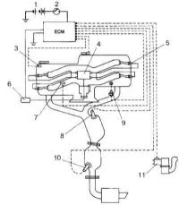
Fig.1.Car wiring diagram ignition systems Subaru Legacy Outback (4-cylinder models).
1 - the Battery
2 - the ignition Switch
3 - the Gauge of position of a cam shaft (GCS)
4 - the Ignition coil
5 - the Spark plug
6 - the ignition Module
7 - the detonation Gauge
8 - the Front oxygen gauge
9 - the Temperature detector of a cooling fluid of the engine (TDC)
10 - the Rear oxygen gauge
11 - the Gauge of measurement of weight of air
On 4-cylinder models of an ignition coil (on one on pair cylinders) are united with the ignition module in uniform assembly as it is shown on car wiring diagram Subaru Legacy Outback.
In system DIS 4-cylinder models Subaru Legacy Outback at ignition distribution the single spark is used. At the command of ECP spark formation occurs in simultan eously two cylinders, the bucket of one of which is in the end of a timing period of compression, another - in the end of a final timing period. Thus the basic power failure is necessary on a candle of the cylinder which is in a timing period of compression in view of much more of a high pressure in it. Capacity spark formation in the second cylinder will be minimum (a single spark), providing thus reburning of molecules of an air-fuel mixture remaining in a combustion chamber that allows to achieve more effective drop of toxicity of the fulfilled gases. Spark formation occurs at a time in cylinders 1/2 and 3/4.
Read more...
For the purpose of air-fuel mixture ignition in cylinders of the engine the system generates high-voltage (HV) pressure and gives out it on screwed in each of cylinders of the engine of a spark plug. Pressure should be high enough to provide "breakdown" of an air spacing between candle electrodes. Besides, "breakdown" should occur during strictly certain moment of time corresponding to current position of the bucket in the cylinder and answering to inquiries of the engine in a wide range of operational parametres.
Fig.1.Car wiring diagram ignition systems Subaru Legacy Outback (4-cylinder models).
1 - the Battery
2 - the ignition Switch
3 - the Gauge of position of a cam shaft (GCS)
4 - the Ignition coil
5 - the Spark plug
6 - the ignition Module
7 - the detonation Gauge
8 - the Front oxygen gauge
9 - the Temperature detector of a cooling fluid of the engine (TDC)
10 - the Rear oxygen gauge
11 - the Gauge of measurement of weight of air
On 4-cylinder models of an ignition coil (on one on pair cylinders) are united with the ignition module in uniform assembly as it is shown on car wiring diagram Subaru Legacy Outback.
In system DIS 4-cylinder models Subaru Legacy Outback at ignition distribution the single spark is used. At the command of ECP spark formation occurs in simultan eously two cylinders, the bucket of one of which is in the end of a timing period of compression, another - in the end of a final timing period. Thus the basic power failure is necessary on a candle of the cylinder which is in a timing period of compression in view of much more of a high pressure in it. Capacity spark formation in the second cylinder will be minimum (a single spark), providing thus reburning of molecules of an air-fuel mixture remaining in a combustion chamber that allows to achieve more effective drop of toxicity of the fulfilled gases. Spark formation occurs at a time in cylinders 1/2 and 3/4.
Read more...


