Jul 29, 2009

Car wiring diagram: replacement of altenator brushes Ford Mondeo.

car wiring diagram
Check of the established generator
During movement of the car the indicating lamp of car wiring diagram gymnastics of the accumulator battery should not burn. Otherwise the generator or a voltage adjuster is faulty. First of all check up all connecting leads of the generator, being verified on car wiring diagram. Then check up a belt tension on a belt pulley and work of an automatic tightener. Other checks are carried out at the removed generator.Do not forget to be verified on wiring diagram.
The established generator is not under repair, at failure it replace with the interchangeable generator on which the guarantee as on the new operates. However in most cases it is possible to inspect the faulty generator in service centre Bosch before installation of the new generator. Thus it can be found out, that the generator can be repaired, if failures are insignificant.


Replacement of altenator brushes on 16-valves the engine spend as follows:


car wiring diagram


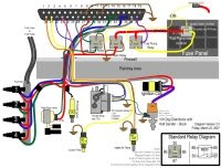
Fig.1. Ford Mondeo car wiring diagram: fastening of an adjuster of the generator on 16-valves the engine.


- Turn out on the rear party of the removed generator bolts of fastening of an adjuster and remove an adjuster;

- Fix a new adjuster on the generator, take out a brush guard pin;
- Establish the generator and connect to the battery;
- Do not forget to be verified on car wiring diagram.


Replacement of altenator brushes by engine V6 spend as follows:


car wiring diagram


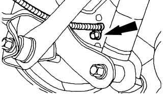
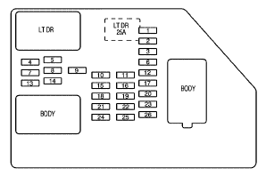
Fig.2. Ford Mondeo car wiring diagram: adjuster fastening to engine V6 generator.


- Turn on on the removed generator a blank-end cover ;

- Turn out bolts of fastening of an adjuster/holder of a brush and take out an adjuster from the generator; - Insert a new adjuster and fix bolts;
- Again establish a blank-end cover, establish the generator and connect it to the accumulator battery;
- Do not forget to be verified on car wiring diagram.

Read more...

Car wiring diagram: block safety locks Mazda 323 1985-1989.

car wiring diagramArrangement of safety locks

The arrangement of safety locks can differ depending on model. The arrangement of safety locks is reflected in a fuse block cover, and also in the car wiring diagram in maintenance manual. The basic safety locks of model Mazda 323 1985-1989 settle down in a box in an impellent compartment, before the left housing of an amortisation rack.


car wiring diagram


Fig. 1.Car wiring diagram arrangements of safety locks Mazda 323.


Appointment of safety locks
1-Electric window regulator
2 -stoplights, sound signal
3- steering of the engine
4 -motor of the compressor (resetting of height of a road gleam) *
5-devices
6 -antifrost screen
7 -rear marker light
8 -radio receiver, lightы resetting of mirrors
9 -rear antifog flashlights
10 -washer of headlights
11 -central stop the device
12 -internal illumination
13 -air conditioner
14 -block distributing box*
15- hatch
16 -system of a window wiper and the window washer
17 -motor of the fan
18 -rear window wiper
19 -fan of a heater
* - only on cars with an all wheel drive

car wiring diagram


Fig. 2.Car wiring diagram appointment of safety locks Mazda 323.


Nominal force of a current of a safety lock costs from an underside on the handle.It is possible to find also onwiring diagram.Besides the handle has a colour designation on which also it is possible to define nominal force of a current.
10 A - red
15 A- dark blue
20 A - yellow
30 A- light green


Read more...

Car wiring diagram and the basic failures of starter Ford Escort 1980-1990.

car wiring diagramThe basic failures and methods of their elimination
1. At inclusion of starter the starter electric motor does not work
1.1. Failure of starter either the traction relay or defect in wires To check up being verified on car wiring diagram pressure presence on the plug 50 traction relays:
- Absence of pressure at starter inclusion testifies to damage wiring diagram an electric circuit
- Pressure presence testifies to failure of the traction relay or a starter
- If at inclusion of a starter pressure moves on the traction relay, but it does not work (there is no characteristic click), means, the traction relay (breakage of a winding or its short circuit on weight) is faulty
- Presence of characteristic click operation the traction relay testifies about scorching relay contacts or to failure of the starter
1.2. The electric motor is faulty
To check up work of the electric motor of a starter as short-term giving of pressure (an additional jump lead) on contact piece of the traction relay from the electric motor, being verified on wiring diagram. If the electric motor starts to work, means, it is necessary to search for a cause of defect in the traction relay


car wiring diagram


Fig.1. Ford Escort car wring diagram: Ford Escort starter Bosch. 1 - head; 2 - drive gear knot; 3 - drive gear lever; 4 - electromagnetic switch; 5 - stator; 6 - rotor; 7 - brush-holder


car wiring diagram


Fig.2. Car wiring diagram: Ford Escort starter Lucas. 1 - head; 2 - drive gear knot; 3 - drive gear lever; 4 - electromagnetic switch; 5 - stator; 6 - rotor; 7 - blank-end cover with a brush-holder


carwiring diagram


Fig.3.Car w iring diagram: Ford Escort starter Nippondenso 1 - head; 2 - drive gear knot; 3 - drive gear lever; 4 - electromagnetic switch; 5 - stator; 6 - rotor; 7 - brush-holder


2. The starter rotates slowly and does not start the engine
2.1. The accumulator is discharged
- To charge the accumulator
2.2. In an engine lubricating system too dense oil is filled in
- To replace oil
2.3. Graphite brushes are insufficiently pressed to a collector of the electric motor of a starter
- To adjust distance between graphite brushes and a collector
2.4. A bad condition of a work face of a collector starter bearings also are worn out
- To check up and, if necessary, to replace worn-out parts

3. At releasing the ignition key from position "starting engine operation" the starter continues to work
3.1. Sticking contact pieces of the traction relay
3.2. The ignition lock does not disconnect a starting circuit
- Immediately to switch off ignition and to disconnect the accumulator, then to eliminate failure.

Read more...

Jul 15, 2009

Car wiring diagram for ECM Pin-out and Connectors 1990 Pontiac Grand Prix 3.1L.

---------------------------------------------------------------------------------------------------
car wiring diagramIn 1990, the base model was dropped in favor of a sedan version (replacing the 6000 which ended production the next year and the Canada-only Tempest), entering production on September 12, 1989. A notable introduction for the Grand Prix in 1990 is the new STE (Special Touring Edition) which replaced the STE model of the Pontiac 6000. In contrast to that model, it trades in all-wheel-drive for the available Turbo 3.1L V6. Standard features include a cassette stereo with equilizer and eight speakers (a compact disc player was optional), remote keyless entry, eight-way power driver's seat with multiple lumbar and sidewing adjustments for both front seat occupants, and a compass/trip computer that was more informative than the units in the SE and turbo coupes. An LE sedan was also available for 1990, standard with a 2.3L Quad 4 engine and a 3-speed automatic, the first use of an inline 4 cylinder engine in a Grand Prix .


car wiring diagram


Fig.1.Car wiring diagram for ECM Pin-out and Connectors 1990 Pontiac Grand Prix 3.1L.


Car Wiring Diagram shows an wiring diagram and electric schematic on 1990 Pontiac Grand Prix 3.1L the engine steering module (ECM), a pin and connectors. 1990 Pontiac Grand Prix 3.1L the engine steering module is defined to steer an engine control system what regulates air/fuel mixture and uses a catalytic converter to minimise quantity of the pollution made from the engine. ECM (look wiring diagram) also supervises the input and exit signals, made by various gauges in systems which engages a vehicle speed sensor, the gauge of level of a cooling fluid, a various temperature detector of air, the pressure control device of air of measures, a coolant temperature detector, the oxygen gauge, the relay of the control over the fan, etc.

Read more...

---------------------------------------------------------------------------------------------------

Ford Mustang EFI Nitrous Oxide System Car Wiring Diagram.

---------------------------------------------------------------------------------------------------
car wiring diagramNitrous is the most cost effective way to increase the performance of an internal combustion engine. The way wiring diagramit works is to increase the amount of oxygen that can be introduced into the cylinder during the intake stroke. With more oxygen, more fuel can be burned, and thus, the engine produces more power. This equation works without exception as long as the proper amount of fuel is added to the cylinder to match the nitrous charge. If the fuel is not added, the engine is forced into a lean condition which causes combustion temperatures to increase, along with the potential for massive engine failure. Following article discusses about the Electronic Fuel Injection Nitrous Oxide System Car Wiring Diagram for Ford Mustang. The nitrous system consists of four main components: nitrous system of delivery, fuel delivery system, system plate, and electric system.


cfr wiring diagram


Fig.1. Ford Mustang EFI Nitrous Oxide System Car Wiring Diagram.


Appropriate and safe wiring of nitrous system also is important for consecutive performance data. Nitrous Works are recommended strongly by use of electric relays, thus a drawn game of force of a current from solenoid coils does not damage switches of activation and to assure appropriate solenoidal function.
Read more...

---------------------------------------------------------------------------------------------------

2002 Nissan Frontier Car Wiring Diagram Electrical System Troubleshooting.

---------------------------------------------------------------------------------------------------
car wiring diagramNissan Frontier - the name for D22 and D40 generations of pickups of Nissan entered in 1998, also was replacement for ageing 1986 Nissan Hardbody Truck. The boundary car wiring diagram Nissan the following wiring diagram and electric search of failures of system asks 2002 series Nissan Frontier.
The electric system covers discussion on Supplemental Restraint System (SRS), air bag, set belt pre-tensioner wiring diagrams and trouble diagnosis, harness connector, standardized relay, power supply routing, ground distribution system,


car wiring diagram


Fig.1. Nissan Frontier car wiring diagram.


combination switch check and replacement, steering switch check, headlamp, parking/license/tail lamps, stop lamps, back-up lamps, front fog lamps, turn signal and hazard warning lamps, illumination, interior room lamp,
meters and gauges, compass and thermometer, wiper and washer, audio system schematic/wiring diagram troubled diagnosis and inspection, audio antenna, door mirror, automatic speed control device, power window, power door lock, remote keyless entry system, smart entrance control, electrical unit locations, harness layout, bulb specifications, and car wiring diagram codes.
Read more...

---------------------------------------------------------------------------------------------------

Jul 13, 2009

Car Wiring Diagram: in flight on Dodge Challenger.

---------------------------------------------------------------------------------------------------
Car Wiring Diagram watches novelties auto industries. Here the Air Forces of the USA have decided to construct something absolutely unreal. The American military men have constructed on money of tax bearers two not that of the car, not that of fighter. As donors have acted Ford Mustang and Dodge Challenger. The first after the spent works has received name X-1, the second - Vapor.
First of all at both masl-karov have replaced standard details of body coal-plastic, having given to appearance much more aggression. To change have undergone wiring diagrams. Lamps of head light at cars blink now, as if landing fires of planes, and the input in interior occurs through guillotine-type doors. But completely to estimate alteration, it is necessary to glance inside. The interior of the Mustang is so well stylised under a fighter cockpit, that it not at once recognise as automobile. The driver sits in the middle in plane armchair, instead of a wheel before it joystick, the plane metre panel with mad quantity of toggle-switches is established.

Is hardly quieter under the certificate of correspondent Car Wiring Diagram, in Vapor which is stylised under the plane-invisible being the Stealth. Instead of habitual pedal of an accelerator - the aviation hand lever of giving of pull-rod, and steering wheels, is more true than steering wheels, here whole two. The quite good car for driving school at the same time has turned out. But whether these samples that what to fly are capable, and at least more or less tolerably to go? We know only, that under Ford's X-1 cowl is 500-strong V8 4.6 with advanced system of cooling, and what interiors at Dodge, and at all is not informed. But in the Air Forces of the USA with pride underline, that both cars are completed with plane helmets.


car wiring diagram


Fig.1. Car Wiring Diagram represents Ford Mustang - X-1.


car wiring diagram


Fig.2. Car Wiring Diagram represents Dodge Challenger - Vapor.


car wiring diagram


Fig.3. Car Wiring Diagram : interior of the Dodge Challenger - Vapor is so well stylised under a fighter cockpit.
---------------------------------------------------------------------------------------------------

Car Wiring Diagram meets " black bison".

---------------------------------------------------------------------------------------------------


According to the International studio of tuning of expensive cars Wald International, given Car Wiring Diagram, the firm expands a firm line of accessories Sports Line Black Bison.
Known Japanese tuning the company has presented R-class Mercedes-Benz in firm black weather-cloth Black bison. Now the German crossover looks much more aggressive, as well as other cars "bison" series. The modifed R-class has received new front and rear bumper, lateral skirts and black radiator enclosure. Also at the car have replaced suspender on sports and have put black wheels.
Also under the message Car Wiring Diagram Japanese tuners have decided to send the design efforts to completion new generation of crossovers Lexus RX.

car wiring diagram


Fig.1.Car Wiring Diagram represents R-class Mercedes-Benz in firm black weather-cloth Black bison.


car wiring diagram


Fig.2. Car Wiring Diagram represents crossover Lexus RX - Black Bison.

---------------------------------------------------------------------------------------------------

Car wiring diagram : 2009 Chevrolet Silverado Instrument Panel Fuse Block and Relay.

---------------------------------------------------------------------------------------------------
car wiring diagramRepresented Car Wiring Diagram 2-Mode Hybrid, the new Chevrolet Silverado Hybrid boasts almost 50% better fuel efficiency over previous model years while maintain 100% of the muscle. Among one of its most impressive features; engaged in Mode 1, the Silverado Hybrid’s wiring diagram propulsion is capable of independently powering the vehicle at low speeds, even while towing at maximum capacity [6,100 lbs]. An new car wiring diagram Electronically Variable Transmission [EVT] is jointly powered by both a 6.0L V8 gasoline engine and 300-volt NiMH battery, boosting the Silverado Hybrid’s overall output to 332-hp. A 2-Mode vehicle-standard regenerative braking system provides a constant source of electric energy that helps the Silverado Hybrid’s 26-gallon fuel tank average a cruising range of over 500 miles.

car wiring diagram


Fig.1.Wiring diagramme Chevrolet silverado the fuseboard relay


Fuse plug function / the Protected Chain

1- Rear Seats

2 - Rear Accessory Power Outlet

3 - Steering Wheel Controls Backlight

4 - Driver Door Module

5 - Dome Lamps, Driver Side Turn Signal
6 - Driver Side Turn Signal, Stoplamp

7 - Instrument Panel Back Lighting

8 - Passenger Side Turn Signal, Stoplamp

9 - Passenger Door Module, Driver Unlock

10 - Power Door Lock 2 (Unlock Feature)

11 - Power Door Lock 2 (Lock Feature)

12 - Stoplamps, Center-High Mounted Stoplamp

13 - Rear Climate Controls

14 - Power Mirror

15 - Body Control Module (BCM)

16 - Accessory Power Outlets

17 - Interior Lamps

18 - Power Door Lock 1 (Unlock Feature)

19 - Rear Seat Entertainment

20 - Ultrasonic Rear Parking Assist, Power Liftgate

21 - Power Door Lock 1 (Lock Feature)

22 - Driver Information Center (DIC)

23 - Rear Wiper

24 - Cooled Seats

25 - Driver Seat Module, Remote Keyless Entry System

26 - Driver Power Door Lock (Unlock Feature)


Circuit breaker - Function / the Protected Chain
LTDR - Circuit breaker of the Power window of the Party of the Driver

Harness connector - Function / the Protected Chain

LTDR - Door Communication of the Harness of the Driver

The case - Harness connector


Read more...
---------------------------------------------------------------------------------------------------

Car wiring diagram : 2007 Suzuki Reno Engine Compartment Fuse Box Relay and Circuit Breakers.

---------------------------------------------------------------------------------------------------
car wiring diagramCar Wiring Diagram studies electric equipment 2007 Suzuki Reno. For 2007 the Suzuki Forenza comes available in sedan or wagon bodystyle; in both automatic and manual transmissions. A 2.0-liter, 143-horsepower, four-cylinder engine powers all models. Standard equipment wiring diagram includes air conditioning with a micron air-filtration system, all power conveniences, heated exterior mirrors, and AM/FM stereo with CD and MP3. Safety features on all models include tire pressure monitor, and dual front and side impact airbags. An optional Convenience Package is available which includes keyless remote entry and cruise control. The Popular Package includes the Convenience Package items and adds a power tilt-and-slide sunroof. The 2007 Suzuki Reno car wiring diagram are protected from short circuits by a combination of fuses, circuit breakers and fusible thermal links in the wiring itself. The engine compartment fuse block / box is located on the driver’s side of the vehicle, near the battery. The following wiring diagram and tables shows each Reno fuse / relay location and its circuit protected.


car wiring diagram


Fig.1.Wiring Diagram Suzuki Reno engine compartment fuse box.


Fuse Circuit Protected/ Usage

HEAD LAMPS - Head Lamp
ECM - Engine Control Module
I/P FUSE - Instrument Panel Fuse
FUEL PUMP - Fuel Pump
A/C - Air Conditioning

HORN - Horn
HI BEAM - Head Lamp High-Beam
DRIVER’S PWR WNDW - Driver’s Power Window

STOP LAMPS - Stop Lamps

DR/LCK - Door Lock

MIR HTD - Heated Mirror

FRT FOG - Front Fog

ILLUM LT - License Plate Lamp, Parking Lamp Left

INJ - Injector
ENG SNSR - EVAP - Canister Purge Solenoid, HO2S, Cooling Fan Relay
LOW BEAM LT - Head Lamp Low-Beam Left
ILLUM RT - Illumination Circuit, Parking Lamp Right

LOW BEAM RT - Head Lamp Low-Beam Right

SPARE - Spare
SPARE - Spare
SPARE - Spare

BATT PWR - Battery Power
ABS - Antilock Brake System
HVAC BLWR - HVAC Blower

IGN 2 - Ignition 2

IGN 1 - Ignition 1
FUSE PLR - Fuse Puller

COOL FAN LOW - Cooling Fan Low

DEFOG - Defog
COOL FAN HI - Cooling Fan High
PWR WNDW - Power Window

Relay Circuit Protected/ Usage

COOL FAN LOW - Cooling Fan Low
FRT FOG - Front Fog
ILLUM - Illumination Relay
A/C CMPRSR - Air Conditioning Compressor
HORN - Horn
DEFOG - Defog
FUEL PUMP - Fuel Pump MAIN - Main Relay
COOL FAN HI - Cooling Fan High

PWR WNDW - Power Window

HEAD LAMPS - Headlamp Relay

Read more...

---------------------------------------------------------------------------------------------------

Jul 5, 2009

Car wiring diagramme: basic wiring diagram electric joints Lexus RX300 .

---------------------------------------------------------------------------------------------------
car wiring diagramCompact off-road car Lexus RX-300 of a category "lux" has appeared in the market in 1998. Base complete set Lexus RX-300 rather rich, but also the list of additions to it enough big, therefore the most popular additions are shown in two "packages" - «Premium» and «Limited», - which provide presence of the leather inner trim decorated by a nut tree, the powerful filter of system of ventilation of interior, and also high quality audiosystem Nacamichi. By request interior it is possible to complete with CD-changer on 6 disks and "neosticking together" mirrors.
Car wiring diagram Lexus RX-300 updated and sated. We bring to attention of the reader wiring diagram points of grounding, central points and sockets in impellent compartment Lexus RX-300, and also the basic characteristics of system of an electrical equipment of the engine.
Pressure of the accumulator battery, В
* it is Completely charged 12.5 - 12.9

* It is charged half 12.3
* It is discharged 11.9

Current of gymnastics of the accumulator battery, A 5

Resistance of gauge CMP, Om
* At temperature-10-50 Celsius degree. 835-1400
* At temperature 50-100 Celsius degree. 1060-1645
Resistance of gauge CKP, Om
* At temperature-10-50 Celsius degree. 1630 - 2740
* At temperature 50-100 Celsius degree. 2065 - 3225
Target current of the generator, A

* On 2000 rpm 20

* Without loading no more than 10

* Under loading not less than 30
Pressure on a voltage adjuster exit (without loading), A

* Generator L3B 13.5 - 15.1
* Generator SC1 13.2 - 14.0
Resistance between slip ringss, the Om
* Generator L3B 2.1 - 2.5

* Generator SC1 2.3 - 2.7

Diameter of slip ringss, mm
* Standard 14.2 - 14.4
* Generator L3B 12.8

* Generator SC1 14.0
Length of a ledge of an altenator brush from its holder, mm
* Standard 10.5

* Generator L3B 1.5
* Generator SC1 4.5
Starter output power, kw 1.4

Ovality of the switchboard of an anchor of a starter, mm 0.05

Diameter of the switchboard of an anchor of a starter, mm

* Standard 30.0

* Minimum 29.0

Ledge of contact pieces of the switchboard of a starter from isolation, mm

* Standard 0.6
* Minimum 0.2
Length of brushes of a starter, mm
* Standard 15.5

* Minimum 8.5

Length of a spring of a brush of a starter the established position, mm
* Standard 17.6 - 23.5

* Minimum 11.8
Deterioration of contact plates of a magnetic clutch of a starter, mm 0.9


car wiring diagramFig.1.Wiring diagram Lexus RX-300 points of grounding, central points and sockets in an impellent compartment


The arrangement of points of grounding is specified (BI, BJ, BK, BL, BM, BN) and (IE, IF, IG, IH) and (EA, EA, EC, ED).
Arrangement of sockets (EA1, EB1, EC1) and central points (E1-E14).

Read more...
---------------------------------------------------------------------------------------------------

Wiring Diagram represents the controller of interface of the personal computer Mercedes-Benz W203

---------------------------------------------------------------------------------------------------
wiring diagramWiring Diagram represents controller of interface of the personal computer with onboard system of self-diagnostics OBD II under reports of standards SAE (PWM and VPW) and ISO 9141-2 Mercedes-Benz W203 .
Main destination
.
To standard VPW answer wiring diagram company GM manufactures, to standard PWM - Ford, to standard ISO 9141-2 - the Asian and European models.
The considered device represents the microcontroller executed on technology (CMOS). The controller is not intended connections to onboard systems of self-diagnostics of the first generation (OBD I), as on Mercedes-Benz W203!
This wiring diagram carries out a role of the elementary scanner and is intended for reading of diagnostic codes and data of system OBD II (engine turns, temperature of a cooling fluid and soaked up air, loading characteristics, the expense of air arriving in the engine, etc.) within the limits of standard SAE J1979 through the tyre of any execution (PWM, VPW and ISO 9141-2). Wiring diagram to the computer it is enough for connection 3-zhilnogo a wire, connection to a diagnostic socket is carried out 6-zhilnym by a wire. The source voltage moves on the controller through 16-contact diagnostic socket OBD. Basic wiring diagram the controller for Mercedes-Benz W203 it is presented on an illustration.

wiring diagramFig.1. Wiring diagram the controller of interface of the personal computer with onboard system of self-diagnostics OBD II under reports of standards SAE (PWM and VPW) and ISO 9141-2 Mercedes-Benz W203 .

Recommendations about application
For connection diagram devices on Mercedes-Benz W203 the cable, length no more than 1.2 m that has special value at use of report PWM can be used not-screened. At use of a cable more lengths it is necessary to reduce resistance of resistors on a device input (R8 and R9 or R15). At use screened cable, the screen should be disconnected for the purpose of capacity drop.
The cable for connection to a serial port of the computer of Mercedes-Benz W203 also can be not-screened . The device stably works with a cable in length to 9 m. At much more length of a cable it is necessary to use more powerful communicator RS 232.
The topology of electric joints according to wiring diagram is any. At the raised moistness apply additional shunting condensers.
The free software (browser) for reading of codes and data for Mercedes-Benz W203 can be downloaded from sites of manufacture and is intended for use under DOS. The insignificant size of a program application in a variant «under DOS» allows to contain it on loading diskette DOS and to use even on the computers equipped incompatible with DOS with the software. An unessential condition is even presence in the hard disk computer.

Read more...

---------------------------------------------------------------------------------------------------
Clean FixSim_112007